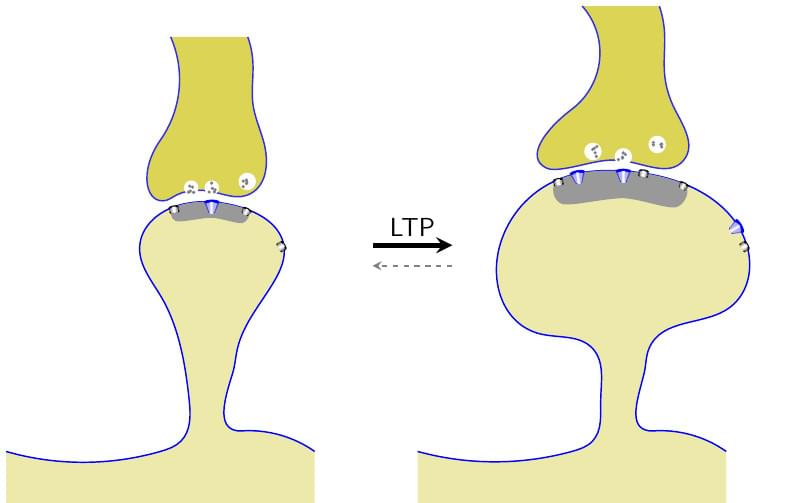
LTP in Synapse
Forfatter:
Dilawar Singh
Sidst opdateret:
6 år siden
Licens:
Creative Commons CC BY 4.0
Resumé:
Long Term Potentiation (LTP) in synapse.

\begin
Discover why over 25 million people worldwide trust Overleaf with their work.
Long Term Potentiation (LTP) in synapse.

\begin
Discover why over 25 million people worldwide trust Overleaf with their work.
% FIGURE shows LTP in spine.
\RequirePackage{luatex85,shellesc}

\documentclass[crop]{standalone}

\usepackage{pgfplots}
\pgfplotsset{compat=1.15}
\usepackage{tikz}
\usetikzlibrary{positioning,calc,shapes,hobby}
\usetikzlibrary{scopes}
\usetikzlibrary{fit}
\usetikzlibrary{intersections, pgfplots.fillbetween}
\usetikzlibrary{arrows}

% Background layer.
\pgfdeclarelayer{bg}
\pgfdeclarelayer{ft}
\pgfsetlayers{bg,main,ft}

\renewcommand{\familydefault}{\sfdefault}
\pgfmathsetseed{10}

\input{structure}
\input{channel}

% Macros
\newcommand\VESICLE[3]{ % name, location, scale
    \def\NODESIZE{1}
    \begin{scope}[shift={(#2)}]
        \node[circle,fill=white, inner sep=#3*\NODESIZE mm] (#1) at (0,0) {};
        \foreach \i in {1,...,5} {
            \pgfmathsetmacro\x{rand*\NODESIZE}
            \pgfmathsetmacro\y{rand*\NODESIZE}
            \node[fill=black!50, draw=none,circle,inner sep=0.7pt] at (\x mm,\y mm) {};
        }
    \end{scope}
}

\begin{document}


\begin{tikzpicture}[hobby]

    \SPINEWITHAXON{S1}{(-4,0)}{0.7}
    \SPINEWITHAXON{S2}{(4,0)}{1.2}

    % Now add some pre-synaptic vesicle
    \VESICLE{v1}{[yshift=0.75mm]S1_PRE_R2}{1}
    \VESICLE{v2}{[shift=(10:7mm)]v1}{1.2}
    \VESICLE{v3}{[shift=(180:4mm)]v1}{1}

    \VESICLE{v1}{[yshift=0.75mm]S2_PRE_R2}{1.2}
    \VESICLE{v2}{[shift=(20:7mm)]v1}{1.2}
    \VESICLE{v3}{[shift=(170:6mm)]v1}{1.2}

    \draw[-stealth, black, line width=1mm] (S1) to[] node[above] {\Large LTP} (S2);
    \draw[-stealth, gray, dashed, very thick] ([yshift=-4mm]S2.west) to[]
        ([yshift=-4mm]S1.east);

    % ADD RECEPTORS ON POST MEMBRANE.
    \CHANNEL{S1_SN1}{0.2}{0.1}{0}{black}{10}
    \CHANNEL{S1_SN2}{0.3}{0.2}{40}{blue}{0}
    \CHANNEL{S1_SN3}{0.2}{0.1}{30}{black}{-30}
    \CHANNEL{S1_SE1}{0.2}{0.1}{0}{black}{-60}

    \CHANNEL{S2_SN1}{0.2}{0.1}{0}{black}{10}
    \CHANNEL{S2_SN2}{0.3}{0.2}{40}{blue}{0}
    \CHANNEL{S2_SN3}{0.2}{0.1}{30}{black}{-30}
    \CHANNEL{S2_SE1}{0.2}{0.1}{0}{black}{-60}

    \coordinate (x1) at ([shift=(110:4mm)]S2_SE1);
    \coordinate (x2) at ([shift=(20:4mm)]S2_SN1);
    \coordinate (x3) at ([shift=(0:4mm)]S2_SN2);

    \CHANNEL{x1}{0.3}{0.2}{40}{blue}{-60}
    \CHANNEL{x2}{0.3}{0.2}{40}{blue}{10}
    \CHANNEL{x3}{0.2}{0.1}{0}{black}{-10}

\end{tikzpicture}

\end{document}